A 7-segment display is a form of electronic display device used for displaying decimal numerals and other characters. It consists of seven individually controllable segments (typically arranged in the shape of the digit '8') that can be turned on or off to display numerical digits (0-9) and some alphabet characters.
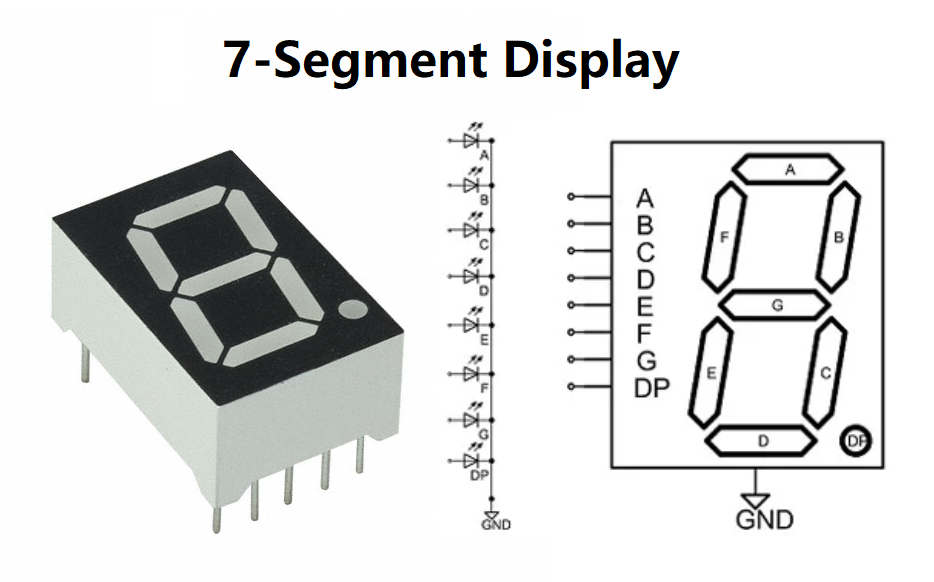
Structure of a 7-Segment Display:
-
Segments:
- Each of the seven segments in the display is designated by a letter (A to G) or by the corresponding bit position (0 to 6).
- These segments are arranged in a specific pattern to represent different numbers and characters.
-
Common Anode vs. Common Cathode:
- In a common anode 7-segment display, all the anodes of the LEDs in the segments are tied together and connected to a positive voltage, while individual cathodes are used to control each segment.
- In a common cathode 7-segment display, all the cathodes of the LEDs are tied together and connected to ground, and individual anodes are used to control each segment.
Functionality and Usage:
-
Numeric Display:
- 7-segment displays are commonly used to display numeric information, typically showing digits from 0 to 9.
- By turning on specific segments in different combinations, different numbers can be displayed.
-
Alphanumeric Display:
- With careful control of the segments, 7-segment displays can also show some alphabet characters and other symbols.
-
Applications:
- Used in a wide range of electronic devices like digital clocks, timers, calculators, microwave ovens, weight machines, and other applications requiring numerical or simple character displays.
Driving a 7-Segment Display:
-
Multiplexing:
- To display multiple digits using fewer pins, multiplexing is commonly employed. This technique cycles through different digits quickly to give the illusion of all digits being displayed simultaneously.
-
Driving Circuits:
- Typically, a current-limiting resistor is connected in series with each segment to protect the LEDs from damage due to excessive current.
- Transistors (such as NPN or PNP transistors) are commonly used to control each segment in a common anode or common cathode configuration.
Advantages:
- Easy to read and understand numerical information quickly.
- Simple and cost-effective solution for displaying numeric characters.
- Low power consumption compared to more complex display technologies.
Limitations:
- Limited to displaying numbers and a few characters.
- Cannot show advanced graphics or full alphanumeric characters without additional components.
7-segment displays are fundamental components in electronic devices for showing numerical information in a clear and concise manner, making them widely used in various applications that require simple numeric or character displays.
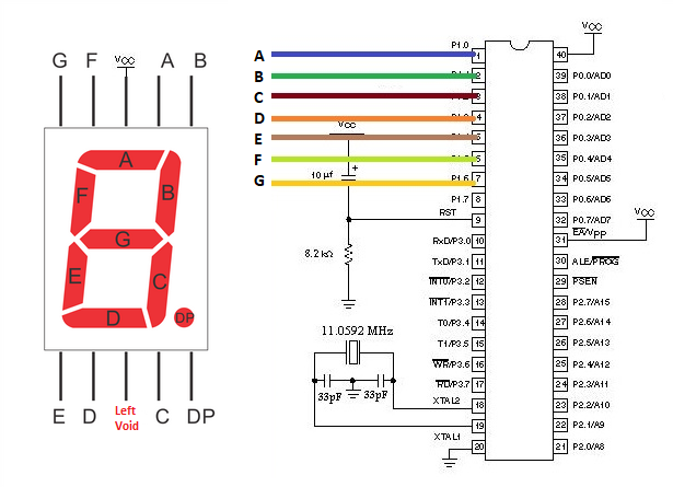
7-Segment Display Pinout
A standard 7-segment display typically consists of seven individual LEDs arranged in a pattern to represent numerical digits from 0 to 9 and sometimes certain alphabet characters. Each of these segments can be controlled independently to display different numbers or characters. The pinout of a common-cathode 7-segment display is as follows:
Common-Cathode 7-Segment Display Pinout:
- Common Cathode Pin (CC):
- This pin is connected to the cathodes of all seven LEDs.
- It is the common connection for the cathodes of all the segments.
- Segment Pins (a, b, c, d, e, f, g):
- These pins are connected to the anodes of the individual LED segments.
- Each pin corresponds to a specific LED segment: a, b, c, d, e, f, g.
Description of Segment Pins:
- a: Segment 'a' represents the top horizontal segment of the 7-segment display.
- b: Segment 'b' represents the top-right segment of the display.
- c: Segment 'c' represents the bottom-right segment.
- d: Segment 'd' represents the bottom horizontal segment.
- e: Segment 'e' represents the bottom-left segment.
- f: Segment 'f' represents the top-left segment.
- g: Segment 'g' represents the middle horizontal segment.
Example Pinout Description:
- Pin 1 (CC): Common Cathode
- Pin 2 (a): Segment 'a'
- Pin 3 (b): Segment 'b'
- Pin 4 (c): Segment 'c'
- Pin 5 (d): Segment 'd'
- Pin 6 (e): Segment 'e'
- Pin 7 (f): Segment 'f'
- Pin 8 (g): Segment 'g'
- Pin 9 (Dot): Decimal Point (if present)
Operating a 7-Segment Display:
- To display a specific digit or character on the 7-segment display, you need to supply power to the common cathode pin (CC) and ground the individual segment pins (a-g) corresponding to the desired numeral or character to be displayed.
- By selectively turning on/off the appropriate combination of segments, different numbers or characters can be displayed on the 7-segment display.
Note:
- The pinout described is for a common-cathode 7-segment display. In the case of a common-anode 7-segment display, the polarity of connections is reversed. The anodes of the LEDs are common, and separate connections are made to the cathodes of individual segments for control.
Understanding the pinout of a 7-segment display is crucial for proper interfacing and control when implementing numeric or character displays in various electronic projects.
The Functioning of the 7-Segment Display
The functioning of a 7-segment display involves lighting up specific segments to represent numerical digits or characters. Each segment (labeled a to g) can be individually controlled to display the desired output. Here's how a 7-segment display works:
Basic Working Principle:
-
Segment Illumination:
- The 7-segment display has a total of seven segments arranged in a specific pattern to form a digit when illuminated in various combinations.
-
Numerical Representation:
- By selectively turning on specific segments, different numbers (0 to 9) and in some cases certain alphabet characters can be displayed.
-
Control Signals:
- To display a particular digit, the corresponding combination of segments needs to be turned on by providing the appropriate control signals to the display.
Displaying Numerical Digits:
-
Each segment is controlled independently, allowing for a wide range of numerical representations.
-
For example:
- To display the digit '0', typically segments 'a', 'b', 'c', 'd', 'e', 'f' are illuminated.
- To display '1', segments 'b' and 'c' are usually used.
- The remaining digits are represented by lighting up specific combinations of segments.
Displaying Letters or Other Characters:
- In addition to numbers, 7-segment displays can show certain alphabet characters by illuminating specific segments. For example, letters like 'A', 'F', 'E', 'C', etc., can be displayed using a 7-segment display.
Control Mechanism:
- Commonly interfaced with microcontrollers or digital logic circuits to control which segments are turned on to display the desired output.
- Each segment is connected to a corresponding pin, allowing for individual control of the segments.
Circuit Connection:
- In a common-cathode 7-segment display, the cathodes of all segments are connected together to a common pin while each anode is connected to a separate pin. The reverse is true for a common-anode display.
Multiplexing:
- To display multiple digits or characters, multiplexing techniques may be used. This involves cycling through each digit rapidly to give the illusion of multiple digits being displayed simultaneously.
Applications:
- 7-segment displays are commonly used in clocks, timers, digital counters, scoreboards, electrical equipment, and many other devices where numerical or limited character displays are required.
Understanding the principles of segment control and display in a 7-segment display is essential for designing circuits or systems that utilize these displays for visual feedback or information presentation.
7-Segment Display Types
There are various types of 7-segment displays available, each with its own features, characteristics, and applications. The two main types of 7-segment displays are common-anode and common-cathode displays. Here is a brief overview of each type:
1. Common-Anode 7-Segment Display:
- Common Connection: All the anodes of the LED segments are tied together and connected to a positive voltage source.
- Segment Control: Each segment is controlled by providing a LOW (logic 0) to illuminate it.
- Operation: A segment is illuminated when the corresponding anode is connected to GND (logic 0).
- Example:
- When you apply GND to the cathode of a specific segment, and a positive voltage to the common anode, that segment will light up.
2. Common-Cathode 7-Segment Display:
- Common Connection: All the cathodes of the LED segments are tied together and connected to GND.
- Segment Control: Each segment is controlled by providing a HIGH (logic 1) to illuminate it.
- Operation: A segment is illuminated when the corresponding cathode is connected to a positive voltage source.
- Example:
- When you apply a positive voltage to the anode of a specific segment and connect the cathode to GND, that segment will light up.
Other Types of 7-Segment Displays:
a. Seven-Segment Numeric LED Displays:
- Purpose: Used primarily for numeric displays (0-9).
- Design: Consist of seven LED segments arranged in the shape of an '8'.
- Application: Commonly found in digital clocks, calculators, and other devices requiring numerical display.
b. Alpha-Numeric 7-Segment Displays:
- Purpose: Can display both numerical digits (0-9) and letters (A-F) or other customized characters.
- Design: Includes additional segments for displaying letters or characters.
- Application: Used in applications requiring a mix of letters and numbers, like digital meters or some types of industrial displays.
c. Multi-Segment LED Displays:
- Purpose: Comprise more than seven segments for displaying more characters.
- Design: Can include additional segments, such as a colon or other symbols.
- Application: Suitable for applications requiring more elaborate displays with additional characters or symbols.
d. Dot-Matrix 7-Segment Displays:
- Purpose: Consist of an array of LED dots forming a matrix for versatile character and graphic display.
- Design: Allows for more complex characters, symbols, and even rudimentary graphics.
- Application: Used in more advanced applications where dynamic display capabilities are needed.
Knowing the different types of 7-segment displays and their characteristics helps in selecting the most suitable type for a particular application based on factors like control method, display requirements, and compatibility with the circuit design.
How Does 7-Segment Display Work?
A 7-segment display works by illuminating specific segments in various combinations to represent numerical digits, letters, or symbols. These displays consist of seven individual LED segments arranged in a specific pattern. Each segment can be controlled independently to display characters. Here's how a 7-segment display works:
Working Principle:
- Segment Illumination:
- The 7-segment display has seven segments (labeled a to g) that can be individually turned on or off.
- Numerical Representation:
- Each segment can be illuminated to display different numbers (0-9) and some alphabet characters (A-F).
- Control Signals:
- To display a specific digit, the corresponding segments need to be turned on by applying the appropriate control signals.
- Displaying Digits:
- Numerical digits (0-9) are formed by turning on specific segments. Each digit can be represented by illuminating a unique combination of segments.
Operation Steps:
-
Segment Identification:
- Each segment is identified by a letter from 'a' to 'g'. For example, 'a' represents the top segment, 'b' is top-right, 'c' is bottom-right, and so on.
-
Digit Display:
- To display a specific digit:
- Identify the segments needed to form that digit.
- Illuminate the corresponding segments by providing the necessary control signals.
- To display a specific digit:
-
Control Method:
- A control system (such as a microcontroller) sends signals to turn on/off the segments.
- Each segment is connected to a pin, allowing individual control.
-
Common Anode vs. Common Cathode:
- In common-anode displays, the common pin is connected to a positive voltage, and segments are turned on by grounding the respective segment pins.
- In common-cathode displays, the common pin is connected to ground, and segments are turned on by applying a positive voltage.
Example:
- To display the number '3' on a 7-segment display:
- Segments 'a', 'b', 'c', 'd', and 'g' need to be turned on while segments 'e' and 'f' are kept off.
- By controlling these segments accordingly, the digit '3' can be displayed.
Applications:
- 7-segment displays are commonly used in digital clocks, calculators, electronic meters, and various devices that require numerical or character displays.
- They provide a simple and cost-effective solution for displaying information in a clear and concise manner.
Conclusion:
Understanding how a 7-segment display works involves knowing how to control individual segments to represent different characters or numbers. By illuminating specific combinations of segments, these displays can effectively showcase numerical data and limited characters for various applications.
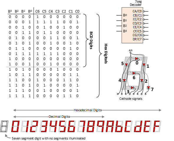
7-Segment Display Codes
To display numbers, letters, and some special characters on a 7-segment display, specific codes are used to activate the segments needed to form each character. These codes vary depending on whether you are working with a common-anode or common-cathode 7-segment display. Below are the common codes used for displaying numbers 0-9 and some letters on a 7-segment display:
1. Common-Anode 7-Segment Display Codes:
2. Common-Cathode 7-Segment Display Codes:
Note:
- Each digit/letter corresponds to the segments that need to be turned on to represent that character on the display.
- 'B' in front of the binary values indicates binary representation.
- The specific combination of segments to turn on/off is determined by the display's wiring (common-anode or common-cathode) and the desired character to be displayed.
By using these codes and sending the corresponding signals to the 7-segment display, you can effectively showcase numbers, letters, and certain characters on the display according to your requirements.
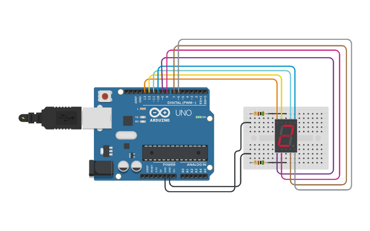
How to use a 7-Segment display
Using a 7-segment display involves sending the appropriate signals to light up specific segments to display numbers, letters, or some special characters. Here is a general guide on how to use a 7-segment display:
Components Needed:
- Common-Anode or Common-Cathode 7-Segment Display: Choose based on your project needs.
- Microcontroller or Arduino Board: To control the display.
- Current-Limiting Resistors: To avoid damaging the LEDs.
- Breadboard and Jumper Wires: For easy connections.
Steps to Use a 7-Segment Display:
-
Identify the Pins:
- Determine which pins correspond to the common anode or cathode and individual segment pins on your 7-segment display.
-
Connect the Display:
- Connect the common pin (anode or cathode based on the type of display) to a power source (Vcc or GND).
- Connect the segment pins to individual output pins on your microcontroller or Arduino.
-
Write the Code:
- Write a program in your preferred programming language to control which segments need to be turned on to display the desired character or number.
- Depending on the display type (common-anode or common-cathode), you will either set the corresponding pins to HIGH or LOW to turn on segments.
-
Display Numbers or Characters:
- Use the appropriate codes for each number, letter, or special character you want to display on the 7-segment display.
- Send signals to the respective pins to display the desired output.
-
Multiplexing (Optional):
- For displaying multiple digits or characters, you can use multiplexing techniques. This involves cycling through different digits rapidly to give the illusion of multiple digits.
-
Testing:
- Upload your code to the microcontroller or Arduino board.
- Power up the circuit and observe the 7-segment display to ensure your program is working correctly.
Example Arduino Code (For Common-Cathode Display):
Conclusion:
By following these steps and properly configuring your circuit and programming, you can effectively utilize a 7-segment display to show numbers, letters, or characters as needed in your electronic projects.